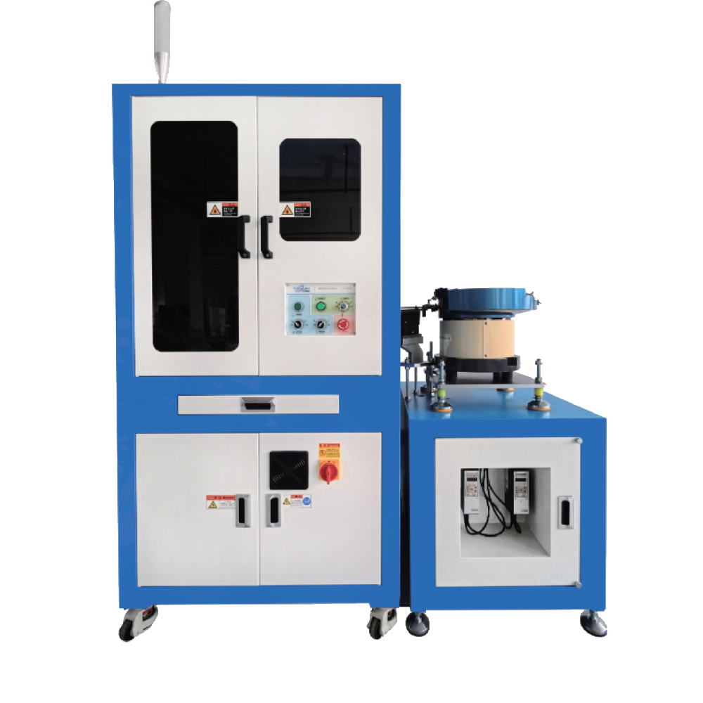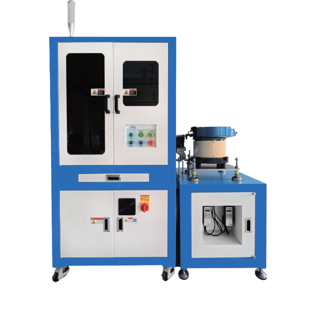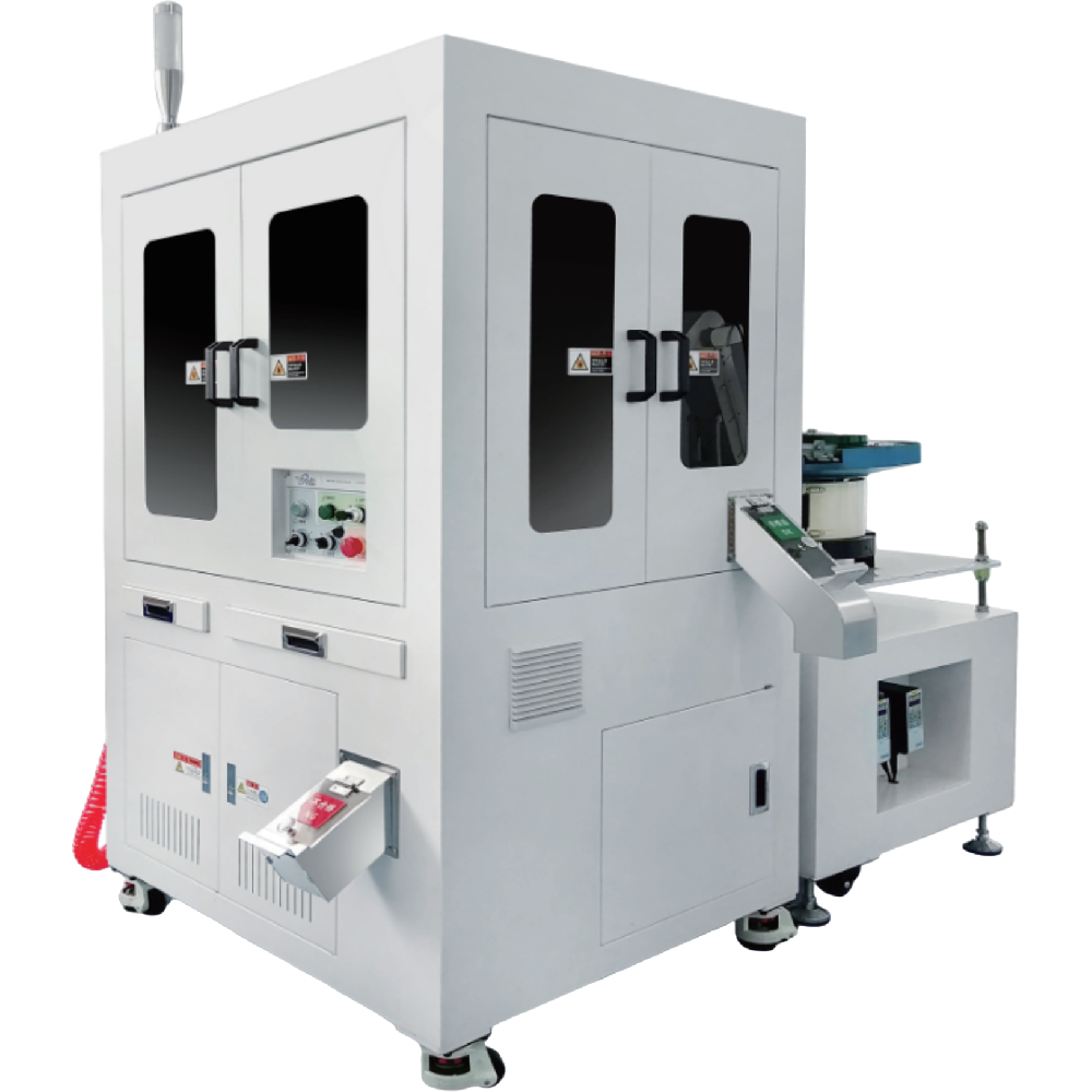
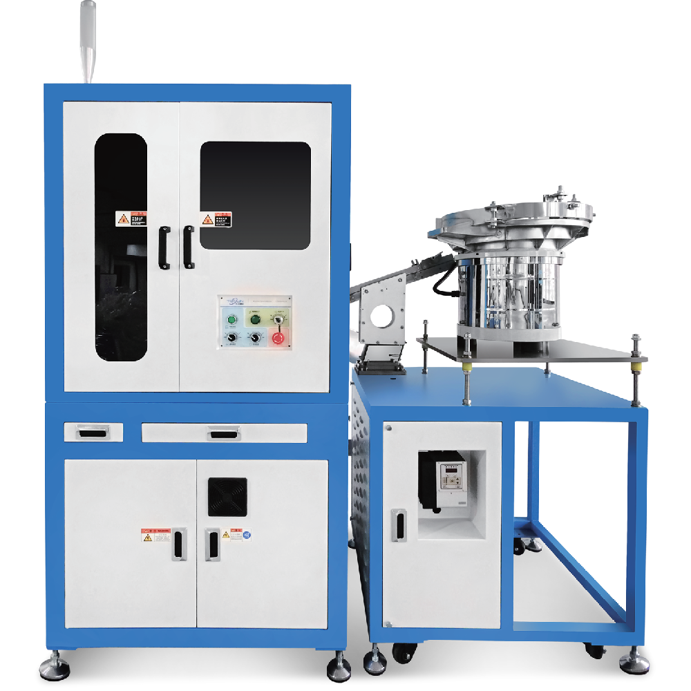
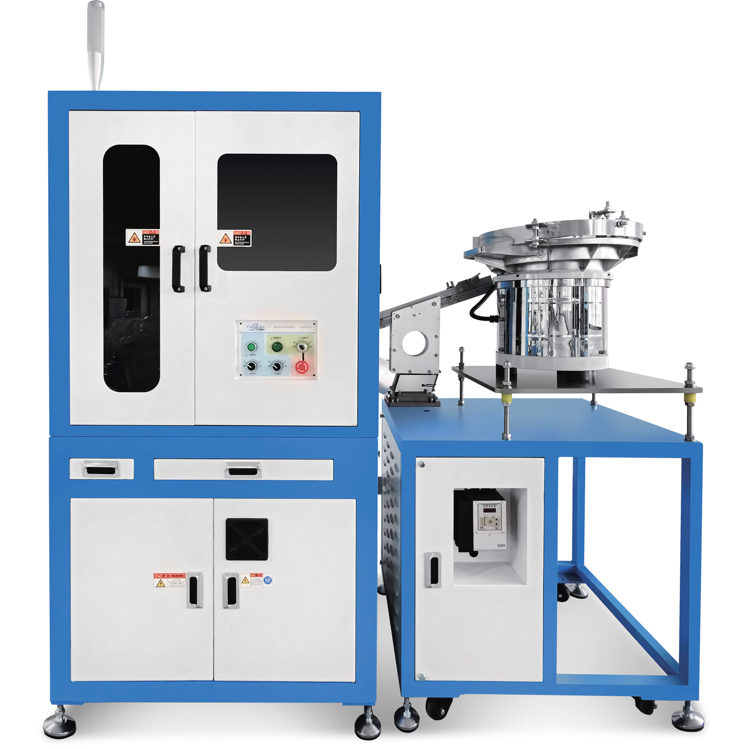
TZF-GD-X(1-12)An indexing disc optical screening machine purpose-built for long-shaft components that cannot feed flat. The suspended indexing mechanism ensures consistent part positioning throughout inspection, with separate modules covering head and shaft zones independently.
Technical Parameters
| Parameter | Specification |
|---|---|
| Model | TZF-GD-X(1-12) |
| Equipment Dimensions (mm) | 1200 × 1200 × 2100 |
| Weight | 850 kg |
| Main Structure | Integrally formed frame, spray-painted baked finish |
| Feeding Mode | Track feeding |
| Inspection Platform | Ø500 mm specialized indexing disc |
| Maximum Camera Count | 12 |
| Industrial Camera | Hikvision / Basler |
| Communication | GigE (Gigabit Ethernet), USB 3.0 |
| Control PC | Industrial-grade IPC |
| Voltage | 220V / 50Hz |
| Pneumatic Pressure | 0.5–0.8 MPa |
Application Parameters
| Parameter | Specification |
|---|---|
| Part Diameter Range | 3–20 mm |
| Part Length Range | 10–200 mm |
| Maximum Throughput | ≤ 800 pcs/min |
| Inspection Accuracy | Up to 0.005 mm |
| Application Industries | General Hardware (long-shaft and structural fastener focus) |
On the length range: The 10–200 mm length capability is the TZF-GD-X(1-12)'s defining specification. No glass disc machine in this product line approaches 200 mm part length; the indexing disc approach makes it possible. Parts in the upper length range (100–200 mm) run at lower throughput due to the longer nest cycle time; our applications team provides throughput estimates based on your specific part dimensions.
Detection capabilities covered:
Total length, outer diameter, step dimensions, thread dimensions
Surface appearance defect detection (head cracks, shaft surface defects, dents, scratches)
Surface character/marking inspection
Head crack and shaft defect detection via dual-module 4-camera opposing configuration
360° circumferential crack detection (with optional external crack lens)
Product Features
Suspended indexing transport — the only right approach for long shafts. When a bolt with a 100 mm grip length tries to travel flat on a glass disc, it sits at an angle relative to its own center of mass. Vibration in the feeding system causes it to shift position between camera frames. The indexing disc nests each part by the head and suspends the shaft, so every part arrives at each camera station in the same defined orientation. This is not an incremental improvement over glass disc transport for these part types — it's a categorically different level of positional repeatability.
Separate inspection modules for head and shaft. Head cracks and shaft surface defects are different in character and typically require different camera positions, lighting angles, and detection algorithms. The TZF-GD-X(1-12) uses separate modular camera groups for the head zone and the shaft zone. Head inspection uses top-down and oblique cameras optimized for detecting radial cracks, bearing surface defects, and socket damage. Shaft inspection uses side cameras at multiple positions for longitudinal cracks, tool marks, and surface irregularities.
Up to 12 inspection cameras. The camera infrastructure supports 12 positions, allocated across head and shaft zones according to the inspection requirement. Customers with complex parts — multi-step shanks, special thread forms, multiple diameter transitions — can assign dedicated cameras to each critical zone.
Optional 360° external crack detection lens. For customers whose primary concern is circumferential cracking at the head-to-shank transition or along the shaft, the 360° lens module provides complete angular coverage with a single camera. It's the fastest way to add circumferential crack coverage without adding multiple side cameras.
Track feeding throughout. Unlike glass disc models that support belt conveyor as an alternative, the TZF-GD-X(1-12) uses track feeding exclusively. This is by design: the suspended indexing mechanism requires parts to be delivered in a consistent upright orientation. Track feeding accomplishes this; belt conveyor feeding for long-shaft parts introduces the same orientation inconsistency the indexing disc is designed to eliminate.
Advantages
1. The right machine for parts that can't lie flat. Glass disc machines have a real operational constraint: they require parts to be stable in a horizontal position. For shaft-heavy fasteners, this simply doesn't apply. The TZF-GD-X(1-12) is built from the ground up for these parts.
2. Up to 200 mm part length — no competitor in this product class matches it. Among glass disc-type machines, the practical length ceiling is around 70 mm. The indexing disc mechanism removes this constraint entirely, handling parts up to 200 mm with the same positional stability as a 20 mm part.
3. Modular head/shaft detection prevents defect categories from interfering with each other. Configuring a single camera module to handle both head surface inspection and shaft crack detection requires compromises in lighting and camera angle. Separate modules mean each inspection zone is optimized independently, and detection parameters for one zone don't affect the other.
4. 4-camera opposing 360° module eliminates angular blind spots. When this module is installed, the combination of head-zone cameras and shaft-zone 4-camera opposing array provides full coverage of the part's exterior surface. There is no angular position where a defect can hide from the inspection system.
5. Industrial build for long-duration continuous operation. At 850 kg, the TZF-GD-X(1-12) is the heaviest machine in this product line. The additional mass comes from a more robust indexing disc drive, the taller enclosure needed for 200 mm part length, and the structural rigidity required to maintain sub-0.01 mm positional repeatability at the indexing stations.
Applications
Long-Shaft Hex Bolts and Structural Fasteners:M5–M20 hex bolts with grip lengths from 20 mm to 150+ mm. These are the hardest parts to run through standard glass disc machines due to their center-of-mass-to-head distance ratio. The TZF-GD-X(1-12) handles them at up to 800 pcs/min with consistent positioning at every camera station.
Anchor Bolts and Foundation Hardware:Anchor bolts and threaded rod sections, typically longer than 100 mm, where thread integrity and shaft surface quality are both critical. The machine can inspect thread pitch consistency, surface cracks, and dimensional compliance (grip length, thread length, diameter transitions) in a single pass.
Studs and Threaded Shafts:Double-ended studs and threaded rod sections in M6–M20 range. These parts are symmetric end-to-end and require shaft inspection across the full length, which is only feasible with suspended transport.
Precision Shafts and Turned Long Components:CNC-turned shafts with tight tolerances on diameter consistency and surface finish, where multiple diameter steps need individual dimensional verification. The multi-camera configuration allows a dedicated camera per diameter step.
Applications where head cracking is the primary rejection criterion:Cold-headed bolts are prone to cracking at the head-to-shank fillet radius under heading stress. The TZF-GD-X(1-12)'s head inspection module, combined with the optional 360° lens, provides the most comprehensive crack detection available in this product class.
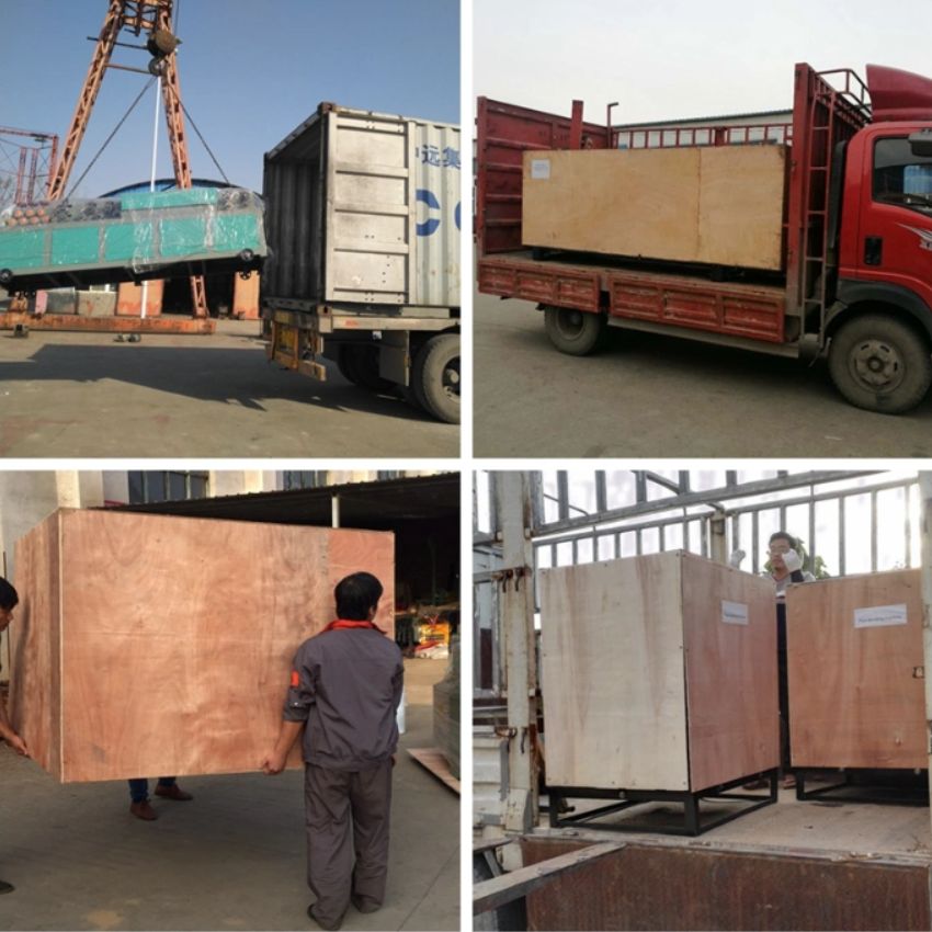
Our Shipping:
AFTER-SALES SERVICE:
1.The whole equipment is guaranteed for one year, and our companysupplies accessories for a long time.
2.To answer technical problems and provide technical services at anytime, three phone calls can not solve the problems, 24 hours to thefactory service.
3.Free training technology until users can independently producequalified products.
4.For all customers who purchase our equipment, our company willprovide the follow-up technical upgrade and improvement of theequipment free of charge.
Frequently Asked Questions (FAQ):
Q: What's the fundamental difference between an indexing disc machine and a glass disc machine?
A:A glass disc machine rotates a transparent disc continuously; parts ride on top of the disc surface and travel past cameras as the disc turns. This requires parts to be stable in the horizontal (lying flat) position. An indexing disc machine moves parts in discrete steps using individual nests that hold each part upright; the disc advances by one position at a time, pausing briefly at each camera station. This approach accommodates parts that can't lie flat (long-shaft components) and provides more stable positioning per camera capture since the part is stationary during each image acquisition.
Q: Does the step-and-pause motion of indexing reduce throughput?
A:Yes, the maximum throughput of 800 pcs/min is lower than glass disc models. This is the inherent trade-off of the indexing mechanism. For customers running long-shaft parts, however, this is not a meaningful constraint — attempting to run 200 mm bolts through a glass disc machine at 1,000+ pcs/min produces unusable inspection results due to positional instability. The TZF-GD-X(1-12) at 800 pcs/min outperforms a glass disc machine running the same parts at any speed in terms of actual detection reliability.
Q: Can the machine handle both the bolt head and the full shaft length in one pass?
A:Yes. The suspended indexing transport positions the part with the head at the top of the nest and the shaft hanging below. Cameras configured for head inspection are positioned at the head level; shaft inspection cameras are positioned along the shaft zone. The machine can cover the full part length from head to tip in a single transport cycle.
Q: What happens if a part falls out of its nest?
A:Parts are secured in nests by geometry — the nest opening is sized to hold the part head while the shaft hangs below. For parts at the extremes of the size range (near Ø3 mm or Ø20 mm), nest sizing is matched during commissioning. Parts that fail to seat correctly are detected by sensors at the entry station and diverted before reaching the inspection zone, preventing false rejects and protecting camera equipment from part collision.
Q: How are rejected parts separated?
A:Rejected parts are ejected from their nests by pneumatic actuators at the rejection station. Multiple reject categories can be directed to separate bins: dimensional rejects, head surface defects, shaft surface defects, and crack rejects can each go to dedicated bins, enabling production engineers to quantify defect distribution and address root causes with specific upstream processes.
Q: Is the TZF-GD-X(1-12) suitable for parts with non-standard head shapes — flange bolts, T-bolts, or special profiles?
A:The standard nest configuration is designed for hex head and socket head profiles. Custom nest inserts can be fabricated for flange heads, T-bolts, and other special profiles. Nest insert fabrication is a standard customization; lead time and cost depend on profile complexity. Contact our technical team with a part drawing to assess nest feasibility.
Q: What's the power consumption of this machine?
A:The TZF-GD-X(1-12) operates on 220V / 50Hz single-phase power. Typical power draw is in the range of 3–5 kW during normal operation. Exact consumption depends on the number of cameras installed and lighting configuration. Our team provides a power specification sheet for facility planning during project scoping.